Visualizing and Refining Our Terrain Survey
Introduction
In the first portion of this exercise, we determined suitable methods for surveying an artificially created terrain. We constructed and recorded our terrain in such a way that the room for error was inherently reduced. One person was in charge of interpreting the elevation of the terrain. If only one person and their one method was used the inherent error with multiple interpretations was drastically reduced. In this exercise we started by importing our elevation data and modelling it within ArcMap 10.2. Elevation data was interpolated using a number of interpolation methods, areas that needed improvement were identified, the terrain was resampled, and finally the terrain was redisplayed using the preferred interpolation method and the newly acquired points.
Methods
To begin this exercise, the elevation data acquired from the first portion of this exercise was imported into Esri ArcMap 10.2 (Figure 1).
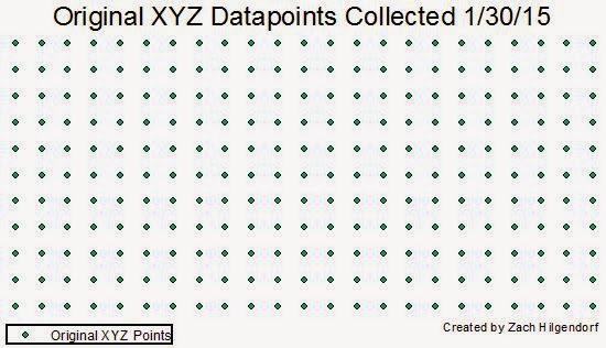 |
| Figure 1. The originally collected data after import into ArcMap. Each of those points has an XYZ designation. |
A continuous surface needed to be created to compare the accuracy of our recording method to the actual terrain. The ability for comparison was achieved by interpolating the points using the Surface Analyst extension using a variety of different methods. Interpolation is the method of predicting the value of cells without data by comparing them with the cells around them and determining a value. There are number of different methods of interpolation available to us using ArcMap such as Inverse Distance Weighted (IDW), Kriging, Natural Neighbor, Spline, Spline with Barriers, Topo to Raster, Trend, and Triangulated Irregular Networks (TIN's). TIN's are not necessarily an interpolation method, as they draw triangles between nodes using Z-values, however they do help us to represent digital elevation models (DEM's). For the purpose of this exercise I will explain only the IDW, Kriging, Natural Neighbor, Spline, and Trend methods of interpolation. The various methods are defined below:
- Triangulated Irregular Network (TIN)
- A method of vector-based surface modeling comprised of nodes, edges, and faces. Nodes are the points that connect to make the edges, while faces are the surface between three nodes. This method forms a series of triangles that vary in size and shape depending on the amount of points in an area (Figure 2).
 |
| Figure 2. The map above is an example of a TIN surface model. Areas where no change in elevation exist appear as flat surfaces while areas with elevation change appear shadowed. |
- Inverse Weighted Distance (IDW)
- A method of interpolation that estimates the value of a cell by averaging the values of neighboring data points. The closer a point is to the center of the estimating cell, the more influence the point has (Figure 3).
 |
| Figure 3. The map above is an example of an IDW surface model. This method estimates cell values by averaging neighboring data points. In this model the presence of circles symbolizes a need for more data points to smooth the terrain. |
- Kriging
- A method of interpolation that estimates surfaces from a scattered set of z-values. It is suggested that for this method more than any other a thorough acquisition of datapoints be conducted to be able to provide the best spatial surface possible (Figure 4).
 |
| Figure 4. The map above is an example of a kriging surface model. This model requires a large collection of datapoints to ensure that the model is smooth. Our model did not necessarily have enough datapoints to create a smooth surface. The circular relics that remain in this model are evidence that not enough points were collected. |
- Natural Neighbor
- A method of interpolation that finds the closest inputs and applies weight to them based upon proportionate values to interpolate a point (Figure 5).
 |
| Figure 5. The map above is an example of a natural neighbor surface model. This model provided a decent representation of our surface though a few relics from the interpolation process did exist, so this method was not chosen for the next step of the process. |
- Spline
- A method of interpolation that estimates values based upon a mathematical function that minimizes overall surface curvature (Figure 6).
 |
| Figure 6. The map above is an example of a spline surface model. This model minimizes the overall curvature of the created surface. The spline model created the surface that most accurately resembled the terrain we created in the planter box. This method was chosen for further use after more points were collected to strengthen the accuracy of the model. |
- Trend
- A method of interpolation that is supposed to fit a smooth surface defined by a mathematical polynomial function. This method is more designed to work with a coarser surface model.
 |
| Figure 7. The map above is an example of the trend surface model. As this model is more fit to deal with coarse surface data and generates a much smoother surface, this interpolation method is not necessarily fit to deal with our model. |
After all of the initial interpolation methods were researched and examined, it was determined that the Spline method gave us the model that most resembled our actual terrain. We then determined areas that could be improved and determined a number of areas that we wanted to resample and increase the amount of points taken (Figure 8).
 |
| Figure 8. The above map shows the original data that was collected for surface modelling in green, with the newly collected points displayed in red. The newly collected points were collected in areas that were determined as needing more detail. |
The spline and TIN creation tools were used again to examine the interpolation of the terrain with the newly added data points (Figure 9 and Figure 10).
 |
| Figure 9. The map above shows what our TIN surface models looks like after more points were gathered to strengthen the detail in the model. |
 |
| Figure 10. The above map shows the spline interpolation method after more points were collected to strengthen the model. An interesting change was noticed using the spline method. When the original points were interpolated using the spline method the results were smooth and did not show many relics of the interpolation method. When the resampled points were added to the model and reinterpolated many relics of the interpolation process remained. |
Discussion
There were a number of issues I encountered when interpolating the newly sampled terrain surface. First off, when we began to sample the new surface the surface had to be cleared off and after a fresh layer of snow had fallen. We cannot say with any certainty whether or not there were significant changes to the terrain that would have altered our results. When I used the newly sampled data to interpolate new surfaces I came across more issues. The spline interpolation, which we selected in the first portion of this exercise because of how well it fit, did not fit well at all when using the new data. There were circular relics of the interpolation process over all of the resampled areas. After checking all the other methods I could not find a method that accurately resembled our terrain, other than the TIN method.
Conclusion
This exercise allowed us to continue developing our critical thinking skills. While we were not able to find a method that accurately and sufficiently resembled our terrain, we did learn a suite of techniques with which to improve our methods in the future. I found that this exercise was a very helpful in developing my methods of project planning. We had to truly think about our methods and develop something that would most accurately represent our model. We also had to learn about interpolation methods and determine which method would accurately represent our terrain. In the future, I feel that I will be able to structure my project more accordingly to the particular situation.
Works Cited
Comparing interpolation methods. Retrieved February 5, 2015, from http://resources.arcgis.com/en/help/main/10.2/index.html#//009z000000z4000000
No comments:
Post a Comment